


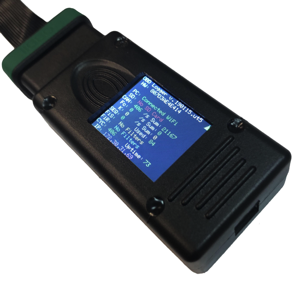
Explanation of the display:
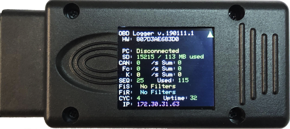
HW: Hardware Serial Number
PC: Connection Status [Disconnected, Connected USB, Connected WiFi, Connected to SERVER]
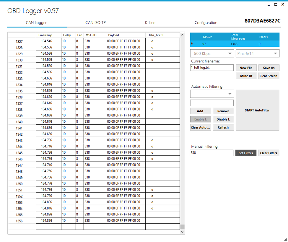
CAN: Can message count before filtering [messages per second/Sum: Total message count]
Fc: Filtered CAN. CAN message count after active filters
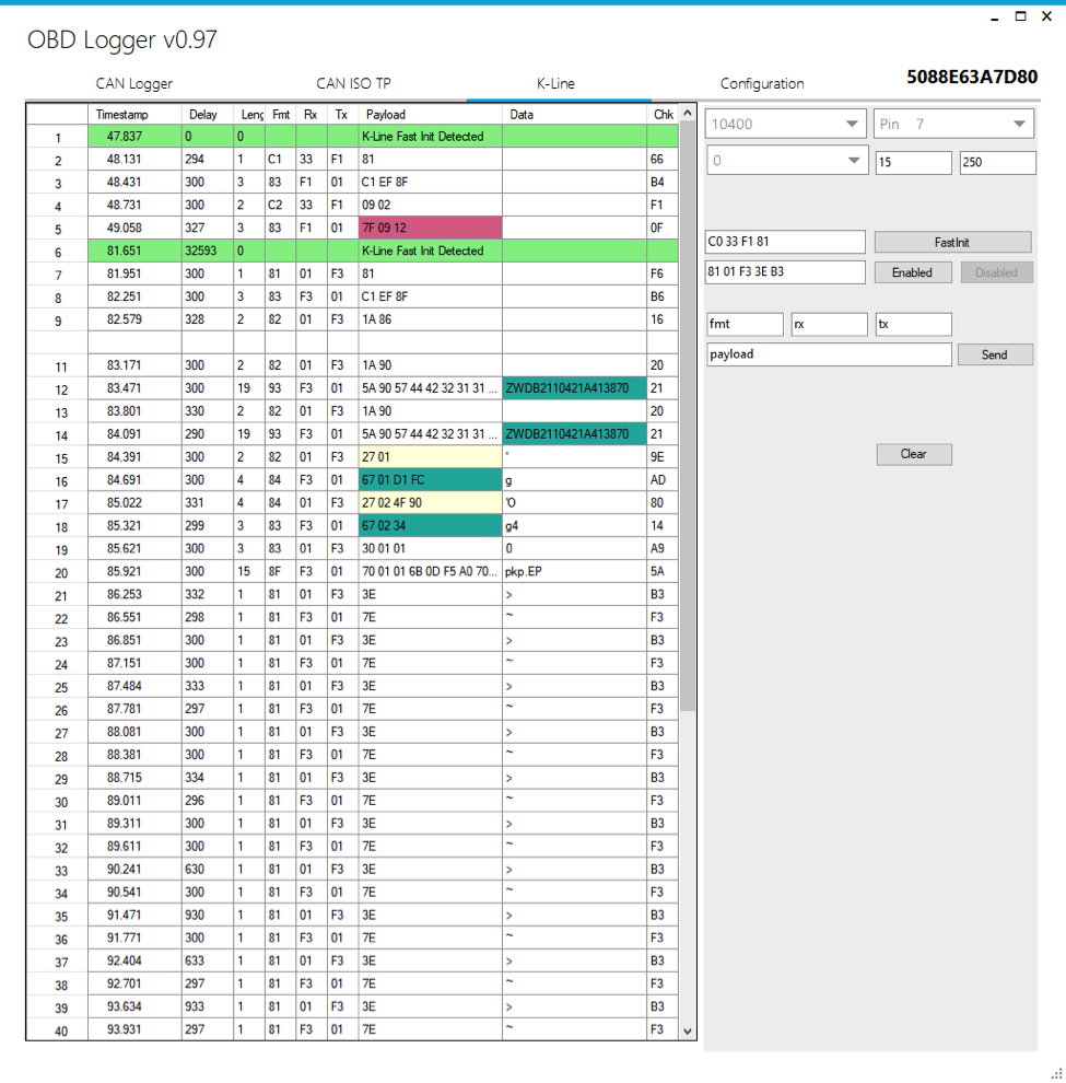
K: K-line information [Bytes per second/ Total bytes]
SEQ: Current sequence of file used for storing logs.
Used: Usage counter. How many times the device have been powered on
FiS: CAN Filter Single. Will show currently used ID for filtering
FiR: CAN Filter Range. Will show the range definition used for filtering can messages
CYC: Only for development
Uptime: Seconds passed after device boot
IP: IP address of device.
Green triangle: Device online and update is up to date.